Effective Module Tilt and Azimuth Angles
Module orientation is specified by nominal tilt and azimuth angles, dictated by the structure upon which the modules are mounted and assuming that structure is positioned on flat horizontal terrain.
The tilt angle is the angle between a normal to the module face, and a normal to a horizontal plane at the same location.
The azimuth angle is the angle between the projection of a normal to the module face onto the horizontal plane and a horizontal line pointing north.
The figure below shows a tilted module and its azimuth relative to north. The global reference frame is green, the rotated reference frame of the module is blue, and the module normal is orange. The module tilt from the vertical axis Z and the module azimuth from north are orange dashed lines, with arrows indicating the positive direction.
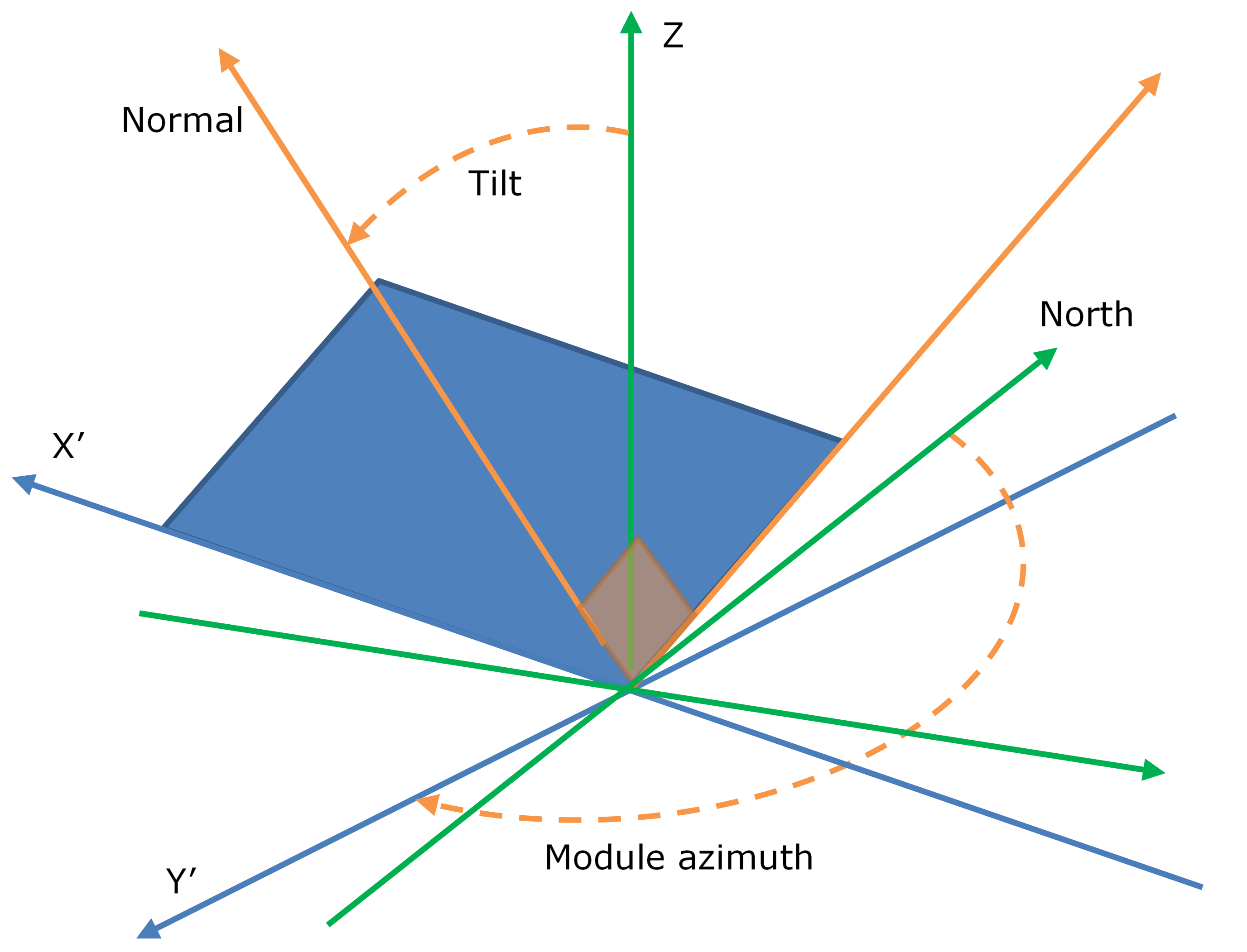
Module tilt and azimuth
As SolarFarmer can consider uneven terrain in its modelling, racks may tilt from end-to-end as well as front to back (or side to side for trackers). Where a rack does tilt from end to end, it is first necessary to calculate the effective tilt and azimuth angles for the rack. It is assumed that the front-to-back tilt remains at the nominal tilt value, with the end-to-end tilt being defined by the terrain. The effective tilt and azimuth angle calculations are described in the rest of this section.
Rack Placement in Uneven Terrain
When a rack is positioned on non-level terrain, the module placement algorithm returns vectors along the two edges of each rack (the "rack edge vectors").
Effective Tilt and Azimuth
Taking the cross product of the rack edge vectors yields a vector normal to the face of the rack. Taking the dot product with a vertical vector gives the effective tilt angle of the rack (\(\beta\)). Projecting this vector onto the horizontal plane and taking the dot product with a north vector gives the effective azimuth angle (\(\gamma\)).