Site Layouts
A site layout defines the instances of all the library objects you have previously added, laid out geographically over the site area. Each workbook has at least one site layout but you may define several. When the energy yield calculation is run you must choose only one of the site layouts.
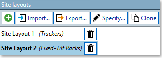
The site layouts in a workbook are accessed (and changed) using the 'Site layouts' panel that appears in the bottom left corner of the 'Lay out plant -> Design layout' task:
Adding a New Site Layout
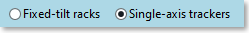
You can add a new site layout by pressing the 'Add' button in the Site Layouts panel. When you add a new site layout, or the first time you use the default site layout in the workbook, you must choose whether to work with fixed-tilt racks or single-axis trackers. You cannot mix fixed-tilt racks and trackers in the same site layout.
Cloning an Existing Site Layout
If you wish to make an exact copy of an existing site layout (you may then want to slightly modify this copy) select the site layout you wish to clone, then press the 'Clone' button in the Site Layouts panel. A new site layout will be created that will be an exact copy of the selected site layout.
Importing a Site Layout
You can import both single-axis trackers and fixed-tilt racks from a file into a site layout.
Note
This functionality is still in beta. It is still in development, especially as there can be a wide variety of data that can be imported from various sources.
Let us know if you see any issues or have any suggestions for how we can improve this.
Importing trackers into a site layout
- Make sure you have a site layout for trackers selected. If not, add a new trackers site layout.
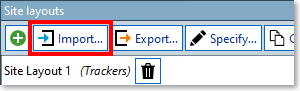
- Press the 'Import...' button in the 'Site layouts' panel to show the 'Import' dialog:
- The 'Import' dialog will appear, with the 'Racks/Trackers' tab selected:
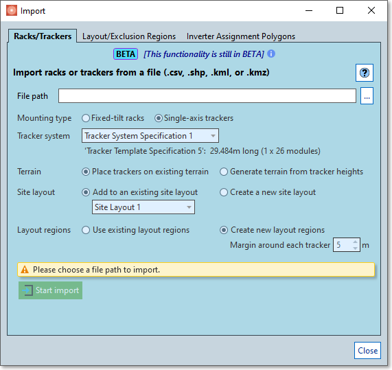
Choose a file containing information that represents the trackers. The following file formats are supported:
CSV (comma separated values) files (
.csv)
Trackers in a CSV file are defined by two points: the mid-point on the tracker's northern edge and the mid-point on the southern edge. This is the only format where the input height of the tracker is taken into account.It assumes that the CSV file has the following 7 headers (separated by a comma): (the actual header text is irrelevant and will be ignored, just the order is important):
Name, X (north), Y (north), Z (north), X (south), Y (south), Z (south)
Followed by one row for each tracker. Any other columns (after these 7 columns) are allowed but will be ignored.The X and Y coordinates of the trackers should be in metres and in the same projection (e.g., UTM Zone 30) as the projection in your workbook. The Z coordinate in metres corresponds to the tracker's height (above sea-level) and not to the ground level below the tracker.
It is important that the decimal separator of the values is a decimal point, and not a comma.
For example:
Name,NorthX,NorthY,NorthZ,SouthX,SouthY,SouthZ
Tracker1,513414.673,4769002.529,308.263,513414.7181587437,4768994.953,308.365
Tracker2,513414.718,4768994.953,308.365,513414.7630041962,4768987.429,308.726
Tracker3,513414.763,4768987.429,308.726,513414.80785140814,4768979.904,308.948
Tracker4,513414.808,4768979.904,308.948,513414.8595937896,4768971.222,309.144
The 'name' value is currently ignored, but may help you distinguish the different trackers.
Shapefiles (
.shp)
Trackers in a shapefile are expected to be represented by a polygon for each tracker.The X and Y coordinates of the polygon points should be in metres and in the same projection (e.g., UTM Zone 30) as the projection in your workbook.
Currently any Z coordinate of the polygon points will be ignored, and it will place the trackers on the existing terrain in the workbook.
Google Earth files (
.kmland.kmz)
Trackers in a Google Earth file are expected to be represented by a polygon or a line path (of which the first and last points will be closed to form a polygon) for each tracker.The X and Y coordinates of the trackers will be in latitude/longitude.
Currently any Z coordinate of the polygon points will be ignored, and it will place the trackers on the existing terrain in the workbook.
PVCollada files (
.pvc) (PVCollada version 1.4.1)
Trackers in a PVCollada file are represented by geometries in the file, and each tracker geometry should have an additional<tracker_parameters>section.The data in a PVCollada file is not geolocated, so to use it in SolarFarmer you first have to position the trackers at the correct location in your site.
Once you have selected your
.pvcfile, click on the 'Position site layout on map' button to position the site:
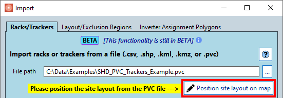
This opens the 'Position Site Layout on Map' dialog.

Click and drag the green trackers to the desired position. It may be slightly tricky to 'grab hold' of the trackers - we will improve this process in the next release.
Different software packages may provide the data in slightly different formats, so there are options to flip the different X, Y and Z components of the points, and swap the Y and Z components. If the site doesn't appear as you expect, try experimenting with the options until it looks as expected. Close the dialog to accept the positions of the trackers and continue with the rest of the import process (the green temporary trackers will disappear).
- Choose the mounting type
- Make sure 'single-axis trackers' is selected for trackers.
- Make sure 'single-axis trackers' is selected for trackers.
- Choose the tracker system to use
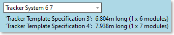
- If you chose a
.pvcfile you have the option to create a new tracker system and tracker templates from the input data. It will do its best to derive the lengths, widths and module layouts in the tracker system and templates. This option is not available when importing from other file formats. - For all file format choices you can choose an existing tracker system from those available in the workbook. The templates are
listed below the mounting system. If there is more than one template the closest template to the length of the
tracker will be chosen for that tracker.
- If you chose a
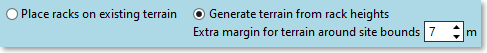
- Choose the terrain options
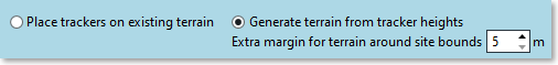
- 'Place trackers on existing terrain' ignores any Z values in the inputs and places the trackers on the existing terrain (like it would if you were adding the trackers with auto-fill).
- 'Generate terrain from tracker heights' (currently only available with the
.csvand.pvcimports) generates an XYZ scatter plot using the north and south points you provide. For each point, the Z value will be the point's Z value minus the 'Min height off ground' value of the tracker system. It then imports the XYZ data as terrain, adding it above any existing terrain in your workbook.- Choose an extra margin value (in metres) from the rectangular area bounds of all the trackers to
to add to the generated terrain (minimum of 5m). This gives a small border around the area of
the trackers.
- Choose an extra margin value (in metres) from the rectangular area bounds of all the trackers to
to add to the generated terrain (minimum of 5m). This gives a small border around the area of
the trackers.
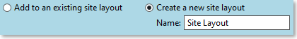
- Choose to add the trackers to an existing site layout, or create a new site layout (with the
specified name).
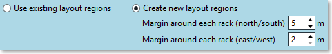
- Choose which layout regions to use:
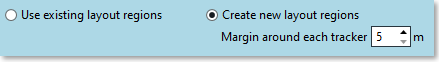
- 'Use existing layout regions' will place the trackers in the existing layout regions in the site layout that you have chosen (you must choose an existing site layout).
- 'Create new layout regions' will create one or more layout regions around the imported trackers.
- Choose margin values around each tracker (separate margin values for north/south, and east/west).
- During the import, neighbouring areas around each tracker will be merged to form bigger layout regions. The larger the margin values, the more likely it will be that the layout regions will be fewer and include more of the trackers. Experiment with different values to see what works best for your site.
There is validation in the dialog to prevent you from making accidental mistakes. Once you're ready, press the 'Start import' button to start the import process.
The import will then proceed (this can take a while if there are lots of trackers). The output from the import will be displayed in an output window in the dialog, giving a summary of what was done, and any errors that may have occurred.
Close the dialog to view your site.
Note, this dialog is just for the import of the racks/trackers. You will have to add inverters and strings as a separate step.
See The Occitaine Tutorial for an example step-by-step tutorial that includes a sample file for this functionality that you can try (specifically the Layout section).
Importing racks into a site layout
This is very similar to the importing trackers description above.
- Make sure you have a site layout for racks selected. If not, add a new racks site layout.
- Press the 'Import...' button in the 'Site layouts' panel to show the 'Import' dialog:
- The 'Import' dialog will appear, with the 'Racks/Trackers' tab selected:
Choose a file containing information that represents the racks. The following file formats are supported:
Shapefiles (
.shp)
Racks in a shapefile are expected to be represented by a polygon for each rack.The X and Y coordinates of the polygon points should be in metres and in the same projection (e.g., UTM Zone 30) as the projection in your workbook.
Currently any Z coordinate of the polygon points will be ignored, and it will place the racks on the existing terrain in the workbook.
Google Earth files (
.kmland.kmz)
Racks in a Google Earth file are expected to be represented by a polygon or a line path (of which the first and last points will be closed to form a polygon) for each rack.The X and Y coordinates of the points will be in latitude/longitude.
Currently any Z coordinate of the polygon points will be ignored, and it will place the racks on the existing terrain in the workbook.
PVCollada files (
.pvc) (PVCollada version 1.4.1)
Racks in a PVCollada file are represented by geometries, and each rack geometry should have an additional<frame_parameters>section.The data in a PVCollada file is not geolocated, so to use it in SolarFarmer you first have to position the racks at the correct location in your site.
Once you have selected your
.pvcfile, click on the 'Position site layout on map' button to position the site:This opens the 'Position Site Layout on Map' dialog.
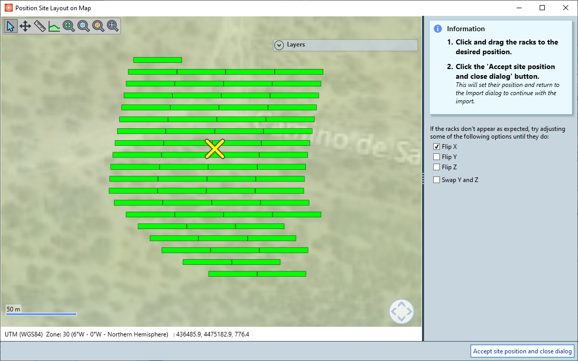
Click and drag the green racks to the desired position. It may be slightly tricky to 'grab hold' of the racks - we will improve this process in the next release.
Different software packages may provide the data in slightly different formats, so there are options to flip the different X, Y and Z components of the points, and swap the Y and Z components. If the site doesn't appear as you expect, try experimenting with the options until it looks as expected. Close the dialog to accept the positions of the racks and continue with the rest of the import process (the green temporary racks will disappear).
- Choose the mounting type
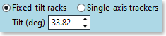
- Make sure 'Fixed-tilt racks' is selected for racks.
- Choose the tilt value to set the racks. It defaults to the default tilt for the site's latitude; set
your own value here if needed.
- Choose the rack system to use
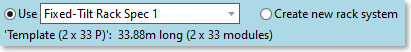
- If you chose a
.pvcfile you have the option to create a new rack system and rack templates from the input data. It will do its best to derive the lengths, widths and module layouts in the rack system and templates. This option is not available when importing from other file formats. - For all file format choices you can choose an existing rack system from those available in the workbook. The templates are
listed below the mounting system. If there is more than one template the closest template to the length of the
rack will be chosen for that rack.
- If you chose a
- Choose the terrain options
- 'Place racks on existing terrain' ignores any Z values in the inputs and places the racks on the existing terrain (like it would if you were adding the racks with auto-fill).
- 'Generate terrain from rack heights' (currently only available with the
.pvcimport) generates an XYZ scatter plot using the lower edge of each rack. For each point, the Z value will be the point's Z value minus the 'Height of lowest edge from ground' value of the rack system. It then imports the XYZ data as terrain, adding it above any existing terrain in your workbook.- Choose an extra margin value (in metres) from the rectangular area bounds of all the racks to
to add to the generated terrain (minimum of 5m). This gives a small border around the area of
the racks.
- Choose an extra margin value (in metres) from the rectangular area bounds of all the racks to
to add to the generated terrain (minimum of 5m). This gives a small border around the area of
the racks.
- Choose to add the racks to an existing site layout, or create a new site layout (with the
specified name).
- Choose which layout regions to use:
- 'Use existing layout regions' will place the racks in the existing layout regions in the site layout that you have chosen (you must choose an existing site layout).
- 'Create new layout regions' will create one or more layout regions around the imported racks.
- Choose margin values around each racks (separate margin values for north/south, and east/west).
- During the import, neighbouring areas around each rack will be merged to form bigger layout regions. The larger the margin values, the more likely it will be that the layout regions will be fewer and include more of the racks. Experiment with different values to see what works best for your site.
There is validation in the dialog to prevent you from making accidental mistakes. Once you're ready, press the 'Start import' button to start the import process.
The import will then proceed (this can take a while if there are lots of racks). The output from the import will be displayed in an output window in the dialog, giving a summary of what was done, and any errors that may have occurred.
Close the dialog to view your site.
Note, this dialog is just for the import of the racks/trackers. You will have to add inverters and strings as a separate step.
Exporting a Site Layout
Press the 'Export...' button to show the 'Export Site Layout' dialog:
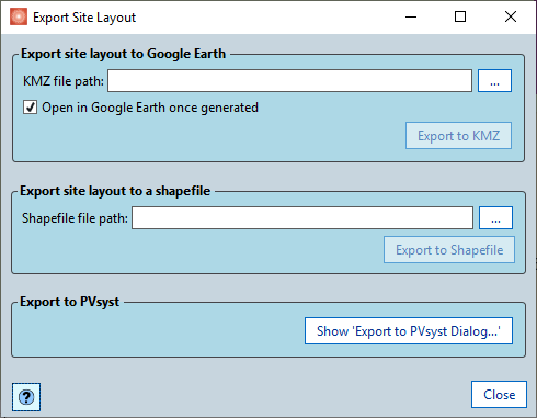
You can export the 3D racks and trackers to 4 file formats:
Export to Google Earth
You can export the 3D racks or trackers to a Google Earth (*.kmz) file for viewing in Google Earth. Once you have chosen a file to export to you can add an optional offset that is added to the locations of the racks/trackers to help compensate for the fact that the background imagery in Google Earth isn't always accurately placed.
Note
You can also export to Google Earth using the scripting function:
Toolbox.Export.ExportSiteLayoutToGoogleEarth(string fullFilePath,
SiteLayout siteLayoutToExport, bool openFileInGoogleEarthAfterExport,
[double eastOffset], [double northOffset]);
Exporting to a Shapefile
You can export the 3D racks or trackers to a shapefile (*.shp). This can then be imported into other software packages such as AutoCAD or GIS software.
One shapefile is exported for the site layout, which contains an area feature for each rack or tracker. The points of each feature contain X, Y and Z coordinates (in the workbook projection). An ELEVATION attribute is also added per feature - this is the minimum Z coordinate for the feature.
Note
You can also export to shapefile using the scripting function:
Toolbox.Export.ExportSiteLayoutToShapefile(
    string fullFilePath, SiteLayout siteLayoutToExport);
Export to PVCollada file
You can export the 3D racks or trackers to a PVCollada (.pvc) file (PVCollada version 1.4.1). This can be then imported into other software packages.
The X and Y coordinates of each point are in metres, and relative to an origin point of the site location. Shading objects in the site layout are currently not included.
Note
You can also export to PVCollada using the scripting function:
Toolbox.Export.ExportSiteLayoutToPvColladaFile(
    string fullFilePath, SiteLayout siteLayoutToExport);
Exporting to PVsyst
You can the site layout to a PVsyst project. See Export to PVsyst for more information on this.
Specify Site Layout Tool
You can lay out sites using parameters (rather than draw them out by hand) using the specify site functionality. Access this using the 'Specify...' button in the Site Layouts panel. See Specify Site Layout Tool for more details on how to use this.