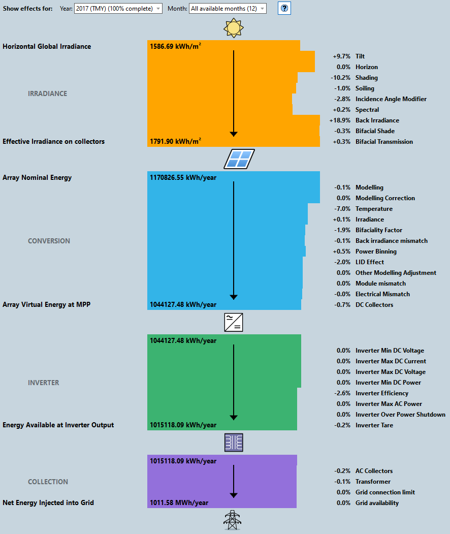
Effects Diagram
Once the energy yield calculation has completed, the effects (gains and losses) are shown in the effects diagram.
It is split into 4 coloured sections that go in/out depending on the size of the loss or gain to give you a visual representation of the values to help identify large changes.
 (click to enlarge)
Irradiance
Sun → Module
Irradiance effects when going from solar input resource to the amount of light available to each module in the PV plant
| Effect | Description |
|---|---|
| Tilt | The irradiance effect going from the Global Horizontal Irradiation to the Global Irradiation incident on each module front side using transposition models. |
| Horizon | The irradiance effect quantifying the amount of irradiance lost due to shading by objects included in the supplied horizon line. |
| Shading | Amount of irradiance lost due to shading on individual modules by other modules, or objects such as trees, terrain and buildings near the PV plant. For bifacial sites run with the cloud calculation, this combines shading for the front and back side of the modules, in all other cases this is the shading for the module front side. |
| Soiling | The reduction of irradiance reaching each module using a simple user-supplied soiling effect. |
| Incidence Angle Modifier | The effects that reduce the amount of irradiance available to the solar cells include reflection from the surface of the module and absorption in the transparent protective layers in front of the cells. This is calculated from Angular Losses Model provided for the PV module |
| Spectral | The effect of the deviation of the actual incident light spectrum from the "AM1.5" spectrum assumed under STC on the power output of PV modules. This is evaluated using the spectral correction model produced by First Solar. |
| Back Irradiance | Only shown for bifacial modules. Irradiance gain due to addition of the module back side for bifacial modules. For local calculations this includes transposition and near shading effects and for cloud calculations, this includes transposition and IAM effects. |
| Bifacial Shade | Only shown for bifacial modules. Structural shading loss for the model back side, using the user input for the layout regions. |
| Bifacial Transmission | Only shown for bifacial modules. Irradiance gain for the model back side accounting for a fraction of light that reaches the back side due to spaces between modules and racks or transparent sections of the modules and racks, using the user input for the layout regions. |
Conversion
Module → Inverter
Energy effects related to the conversion of the available light to electrical power up to inputs to the inverters.
| Effect | Description |
|---|---|
| Modelling | The effect on the energy output caused by the discrepancy between module nominal power and the modelled maximum power point at STC. This can be compensated by setting the Modelling Correction Effect specified for the PV module. |
| Modelling correction | The effect on the energy output when considering the Modelling Correction Effect specified for the PV module. |
| Temperature | The effect on the energy output for the plant operating at the modelled cell temperature instead of 25 °C reference conditions |
| Irradiance | The effect on the energy output for the plant operating at the modelled effective irradiance instead of 1000 W/m2 reference conditions. |
| Bifaciality Factor | Only shown for bifacial modules. The effect on the energy output when considering the efficiency to convert back side irradiance to electricity, using the bifaciality factor specified for the PV module. |
| Back irradiance mismatch | Only shown for bifacial modules. Only shown for bifacial modules. The effect on the energy output when considering the non-uniform backside irradiance, using the mismatch factor specified for the layout regions. |
| Power Binning | The effect on the energy output when considering the power binning specified for the PV module. |
| LID Effect | The effect on the energy output when considering the light induced degradation specified for the PV module. |
| Other Modelling Adjustment | The effect on the energy output when considering Other Modelling Adjustment specified for the PV module. |
| Module Mismatch | The effect on the energy output when considering variations in module performance, using the Module Mismatch specified for the energy calculation. |
| Electrical Mismatch | The effect on the energy output when considering electrical mismatch caused by connecting the modules in strings. |
| DC Collectors | The effect on the energy output when considering DC connection losses, using the DC Collection Effect specified for the individual inverters in the layout regions. |
Inverter
Inverter → Transformer
Energy effects related to the behaviour of the inverters, modelling its effects on the array AC power output.
| Effect | Description |
|---|---|
| Inverter Min DC Voltage | The effect on the energy output when considering the inverter minimum DC voltage specified in the inverter specification. |
| Inverter Max DC Current | The effect on the energy output when considering the inverter maximum DC current specified in the inverter specification. |
| Inverter Max DC Voltage | The effect on the energy output when considering the inverter maximum DC voltage specified in the inverter specification. |
| Inverter Min DC Power | The effect on the energy output when considering the inverter minimum DC power specified in the inverter specification. |
| Inverter Efficiency | The effect on the energy output when considering the efficiency of the inverter to convert DC power to AC power specified in the inverter specification. |
| Inverter Max AC Power | The effect on the energy output when considering the inverter maximum AC power specified in the inverter specification. |
| Inverter Over Power Shutdown | The effect on the energy output when considering conditions when the inverter is forced to shut down as there is no operating state that observes all the inverter constraints. |
| Inverter Tare | The effect on the energy output when considering the inverter night-time tare loss specified in the inverter specification. |
Collection
Transformer → Grid
Energy effects related to the behaviour of the AC collection network to evaluate the amount of power delivered to the metering point of the PV plant.
| Effect | Description |
|---|---|
| AC Collectors | The effect on the energy output when considering AC connection losses, using the AC Collection Effect specified for the individual inverters in the layout regions. |
| Transformer | The effect on the energy output when considering transformer losses as specified in the transformer specification |
| Grid connection limit | The effect on the energy output when considering the grid connection limit, using the limits specified for the energy calculation. |
| Grid availability | The effect on the energy output when considering the grid availability, using the grid availability loss specified for the energy calculation. |