Layout optimisation in complex terrain
There are many possibilities when doing layout optimisation in PV plants. For example, you can use SolarFarmer to evaluate several layout parameters (e.g., pitch and tilt) as in the example of layout parameters optimisation or you can apply more sophisticated design algorithms to account for terrain complexity and vary pitch of fixed-tilt sites based on the terrain slope.
This mini-tutorial is an advanced optimisation example providing an additional approach to layout optimisation in SolarFarmer, expanding the example to vary pitch with slope magnitude for a range of critical solar elevation angles (i.e., the main parameters driving the algorithm to vary pitch with slope) while targetting a desired DC capacity power for the PV plant.
The script finds the optimal layout based on the vary pitch by slope algorithm and the desired DC capacity limit. Then, it strings the racks to the inverters allowing for unbalanced DC/AC ratios in the inverters within each individual layout region. Finally, the script can run the energy calculation of the optimised layout if chosen by the user.
Note
This script only works for fixed-tilt rack site layouts. There may be a similar one in future for single-axis tracker sites.
Requirements
You need an existing SolarFarmer workbook, with racks already defined and set up, ready to lay out a site and run the energy calculation. See the section Prepare your SolarFarmer workbook further below.
How to use the script
Download the following zip file: "Vary pitch by slope on DC capacity limit.zip".
Open the zip archive and save the enclosed "Vary pitch by slope on DC capacity limit.cs" script file to a folder.Import the script into your workbook:
- Open the Script Editor (see Script Editor)
- Click the 'Import' button in the ribbon:
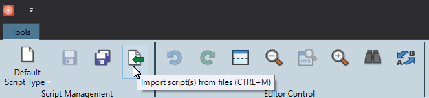
- Select the downloaded script to import
Go to the 'Layout > Design layout' screen in SolarFarmer
Important
This step is important! Otherwise the layout regions won't update
Make sure that the rack system specification is set for each of the layout regions (as the script needs to know the size of each rack)
In the
Execute()function in the 'Vary pitch by slope on DC capacity limit', you will need to define the input data to consider. See further down the description of the inputs.Run the script and the observe the results showed by the command prompt and the final optimised layout region.
1. Prepare your SolarFarmer workbook
This assumes you have an existing SolarFarmer workbook that you have set up and is ready to run a calculation. The workbook should include:
- The site location (and the projection is set)
- Terrain data
- A solar resource
- A module specification, inverter specification, transformer specification and a rack specification.
- Ideally one or more initial layout regions that you plan on filling.
All other parameters (albedo, calculation parameters) have been set, ready to run the energy calculation.
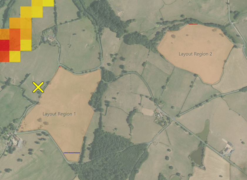
The site layout can have one or more empty layout regions as shown below:
2. Script description
The optimisation script is shown here broken down into several sections to ease the explanation of the different steps of the layout optimisation process. The sections of the script are:
Introduction of input data;
Recreation of the site layout for each critical solar elevation angle;
Reproduction of the optimised layout;
Stringing of the optimised layout using the Specify Site tool scripting;
Update additional layout parameters;
Report the optimisation process summary and run energy calculation for the optimised layout.
Note
The script sections shown in this mini-tutorial omit the several functions called.
The complete code is available in the zip file: "Vary pitch by slope on DC capacity limit.zip".
Section 1: Introduction of input data
The script requires several user inputs to run, which are described below by thematic category. Note that the script includes a minor validation of some inputs, but this is not extensive.
| Variable name | Type | Definition |
|---|---|---|
| General data | ||
| returnOnlyOptimizedLayout | bool | Choose if you want a separate site layout for each layout variant evaluated or only the final resulting layout. |
| runEnergyCalculationForOptimizedLayout | bool | Choose whether to run the energy calculation for the optimised layout. |
| parentResultsFolderPath | string | Directory for the results files if decided to run the energy calculation. |
| Layout details | ||
| setbackValue | double | The setback value (in metres) to be used around the inside perimeter of all layout regions. |
| rackAzimuthValue | double | The azimuth value (in degrees) for the rack system. |
| tiltAngle | double | The tilt angle (in degrees) for the rack system. |
| targetDcCapacity | double | The target DC capacity limit (in MWdc). The layout with the closest DC capacity to this value will be returned as the optimal layout. |
| desiredDcAcRatio | double | The desired DC/AC ratio for the plant. |
| criticalSolarElevationInDegreesMinValue | double | The minimum critical solar elevation angle (in degrees) to sweep from. |
| criticalSolarElevationInDegreesMaxValue | double | The maximum critical solar elevation angle (in degrees) to sweep to. |
| criticalSolarElevationInDegreesStep | double | The solar elevation angle step (in degrees). It will loop from the minimum to the maximum values at this step value. |
| maxPitchAllowed | double | Maximum pitch allowed in the layout in case the algorithm converges in an unrealistic solution. |
| Stringing details | ||
| moduleName | string | Select the module to use from those defined in 'Component > PV modules'. A partial name match will be searched. |
| inverterName | string | Select the inverter to use from those defined in 'Component > Inverters'. A partial name match will be searched. |
| evenLoading | bool | Choose how to distribute any strings that lead to non-balanced DC/AC ratio among the inverters in a layout region. If true, the algorithm will distribute any extra strings among the number of inverters defined in 'inverterDifferentIfIrregularLoading'. If false, any strings variation is assigned to a single inverter. |
| invertersDifferentIfIrregularLoading | int | The number of inverters taking the extra strings if the DC/AC ratio doesn't have full inverters. |
| Other modelling details | ||
| thermalUc | double | The constant heat transfer coefficient for the PV module thermal model. |
| thermalUv | double | The convective heat transfer coefficient for the PV module thermal model. |
| cablingAcLosses | double | The collection effects in the AC site (in per unit). |
| cablingAcLosses | double | The collection effects in the DC site (in per unit). |
Section 2: Recreation of the site layout for each critical solar elevation angle
This part of the script generates a layout variant for each critical solar elevation angle using the layout region(s) as reference. Once a layout variant is created, its estimated DC installed capacity (the capacity is all the racks in the site would be strung to inverters) is stored in a dictionary. Finally, the layout is kept or deleted based on the value of the variable returnOnlyOptimizedLayout.
The generation of a specific layout variant follows the principle of the optimisation layout example Vary pitch with Slope.
// Delete all but the first site layout in the workbook then get a reference to the first
// site layout; its layout regions will be used in the new site layouts
DeleteSiteLayouts(Workbook.Domain.SiteLayouts, 1);
SiteLayout templateSiteLayout = Workbook.Domain.SiteLayouts.First();

// Dictionary to store the estimated DC capacity
Dictionary<double, double> DcPowerEstimatedCapacityPerLayout =
    new Dictionary<double, double>();

bool isSouthernHemisphere = Workbook.Domain.Site.Latitude < 0;

for (double criticalSolarElevationInDegrees = criticalSolarElevationInDegreesMinValue;
criticalSolarElevationInDegrees <= criticalSolarElevationInDegreesMaxValue;
criticalSolarElevationInDegrees += criticalSolarElevationInDegreesStep)
{
    // Clone the template site layout and give it a unique site layout name
    // (based on the critical elevation angle values)

    SiteLayout clonedSiteLayout = Workbook.Domain.CloneSiteLayout(templateSiteLayout);
    clonedSiteLayout.Name = string.Format("Crit. elevation angle {0}deg",
        criticalSolarElevationInDegrees);
    Toolbox.Log("Processed new site layout: " + clonedSiteLayout.Name);

    // Set the visible site layout to the newly created one, so that the visuals are updated
    Workbook.Domain.VisibleSiteLayout = clonedSiteLayout;

    // Process the site layout for the specific critical solar elevation angle
    ProcessVaryPitchForSite(clonedSiteLayout, setbackValue, rackAzimuthValue, tiltAngle,
    criticalSolarElevationInDegrees, maxPitchAllowed, isSouthernHemisphere);

    // Add the estimated DC capacity of the layout to the results list
    double dcCapacityInSiteLayout = clonedSiteLayout.Statistics.PvSystemStatistics
                                                    .First().EstimatedDcCapacity;
    DcPowerEstimatedCapacityPerLayout.Add(criticalSolarElevationInDegrees,
                                          dcCapacityInSiteLayout);

    if (returnOnlyOptimizedLayout)
    {
        // Delete the layout if only the optimized layout was requested
        DeleteSiteLayouts(Workbook.Domain.SiteLayouts, 1);
    }
    else
    {
        continue;
    }
}
Section 3: Reproduction of the optimised layout
In this section of the script, layout variant with the closest DC capacity to the desired PV plant DC capacity is designated as the optimised layout. The final layout is then reproduced. If the user chose to keep only the optimised layout, this only is built from the critical elevation angle. Otherwise, the specific layout variant is cloned and renamed.
// Find the layout variation with the closest DC capacity to the target PV plant capacity
KeyValuePair<double, double> closestLayout = DcPowerEstimatedCapacityPerLayout
                   .OrderBy(pair => Math.Abs(pair.Value - targetDcCapacity * 1000)).First();

SiteLayout finalSiteLayout = templateSiteLayout;

if (returnOnlyOptimizedLayout)
{
    // Generate final target layout
    finalSiteLayout = Workbook.Domain.CloneSiteLayout(templateSiteLayout);

    // Process the site layout for optimized layout
    Toolbox.Log("Processing optimized site layout: " + finalSiteLayout.Name);
    ProcessVaryPitchForSite(finalSiteLayout, setbackValue, rackAzimuthValue,
        tiltAngle, closestLayout.Key, maxPitchAllowed, isSouthernHemisphere);
}
else
{
    // Clone the existing optimized site layout
    string optimizedLayoutName = string.Format("Crit. elevation angle {0}deg",
                                               closestLayout.Key);
    finalSiteLayout = Workbook.Domain.CloneSiteLayout(Workbook.Domain.SiteLayouts
                                     .First(s => s.Name == optimizedLayoutName));
    Toolbox.Log("Processed " + finalSiteLayout.Name);
}

finalSiteLayout.Name = string.Format("Optimized layout (sun angle {0}deg; {1} MW)",
    closestLayout.Key, Math.Round(closestLayout.Value / 1000, 2));

Toolbox.Log("Processed " + finalSiteLayout.Name);

// Set the visible site layout to the newly created one, so that the visuals are updated
Workbook.Domain.VisibleSiteLayout = finalSiteLayout;
Section 4: Stringing of the optimised layout using the Specify Site tool
This section estimates the number of inverters and their DC/AC ratio loading to string all the racks present in the layout region(s) in the optimised site layout after the algorithm of vary pitch with terrain slope.
The stringing methodology utilizes the scripting option of the Specific Site tool with the filling option of inverter and modules count, whose values are estimated from the estimated DC capacity for each inverter with a different string loading.
// Add transformer and inverters to the optimised layout.
// If not defined in the layout, add transformer instance to the layout
// (placed an offset from the bottom left coordinate of the first layout)
int trafoNb = finalSiteLayout.TransformerInstances.Count();
if (trafoNb == 0)
{
double offsetForTransformer = 500;
double trafoX = templateSiteLayout.LayoutBoundaries.First()
.Bounds.BottomLeft.X - offsetForTransformer;
double trafoY = templateSiteLayout.LayoutBoundaries.First()
.Bounds.BottomLeft.Y - offsetForTransformer;
finalSiteLayout.AddTransformerInstance(new Location(trafoX, trafoY),
Workbook.ComponentLibrary.TransformerSpecifications.First());
}
// Select library components
ModuleSpecification moduleSpecification = Workbook.ComponentLibrary.ModuleSpecifications
.First(s => s.Name.Contains(moduleName));
InverterSpecification inverterSpecification = Workbook.ComponentLibrary.InverterSpecifications
.First(s => s.Name.Contains(inverterName));
double layoutRegionModulePower = moduleSpecification.Pnom; // in Watts
double inverterNominalPower = inverterSpecification.PnomAC / 1000; // in kW
// Specify site tool - the layout regions will be filled by component numbers.
// The algorithm estimates the numbers of components needed based on the estimated DC capacity in each layout.
SpecifySiteDefinition specifySiteDefinition = new SpecifySiteDefinition
{
// Choose how to fill. We'll choose 'Specify by Module and Inverter Counts'
SpecifySiteConfiguration = SpecifySiteConfiguration.SpecifyModuleAndInverterCounts,
// Set how to fill the layout regions (we use 'fill specific layout regions')
SpecifySiteLayoutRegionFillChoice = SpecifySiteLayoutRegionFillChoice.FillSpecific,
};
List<SubArray> arrayListForSpecifyTool = new List<SubArray>();
// Iterate over each layout region and estimate the number of strings in each inverter.
// It accounts for irregular string distribution (uneven DC/AC ratio) among inverters.
for (int i = 0; i < finalSiteLayout.LayoutBoundaries.Count(); i += 1)
{
string layoutRegionName = finalSiteLayout.LayoutBoundaries.ElementAt(i).Name;
// Estimate total number of strings
double dcCapacityInLayoutRegion = finalSiteLayout.Statistics.
LayoutBoundaryStatistics[i].EstimatedDcCapacity;
double numberModules = dcCapacityInLayoutRegion * 1000 / layoutRegionModulePower;
int totalStringNumberInLayout = (int)numberModules / stringLength;
// Estimate total number of full inverters
double AcCapacityExpected = dcCapacityInLayoutRegion / desiredDcAcRatio;
int numberInvertersFull = (int)Math.Round(AcCapacityExpected / inverterNominalPower, 0);
double AcCapacityApplied = inverterNominalPower * (double)numberInvertersFull;
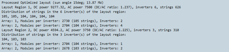
Toolbox.Log(string.Format("{0}, DC power {1}, AC power {2} (DC/AC ratio: {3}), " +
"inverters {4}, strings {5}",
layoutRegionName, dcCapacityInLayoutRegion,
AcCapacityApplied,
Math.Round(dcCapacityInLayoutRegion / AcCapacityApplied, 3),
numberInvertersFull, totalStringNumberInLayout));
// Estimate the string distribution over the inverters in the layout region
int[] initialAssignment = DistributeStrings(totalStringNumberInLayout, numberInvertersFull,
invertersDifferentIfIrregularLoading, evenLoading);
Toolbox.Log(string.Format("Distribution of strings in the {0} inverter(s) of the layout region:", numberInvertersFull));
Toolbox.Log(string.Join(", ", initialAssignment));
List<SubArray> arraysInLayout = GetSpecificArrayNumbers(initialAssignment,
stringLength, layoutRegionName);
arrayListForSpecifyTool.AddRange(arraysInLayout);
}
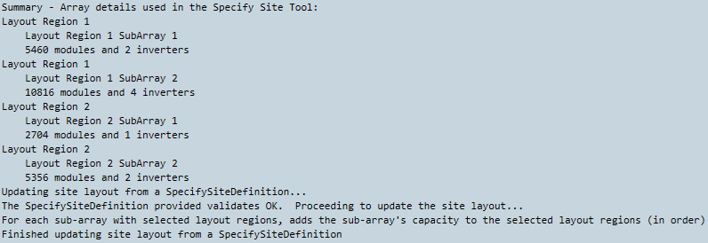
Toolbox.Log("Summary - Array details used in the Specify Site Tool:");
foreach (SubArray subarray in arrayListForSpecifyTool)
{
Toolbox.Log(subarray.SelectedLayoutRegionNames.First().ToString());
Toolbox.Log("\t" + subarray.Name.ToString());
Toolbox.Log("\t" + subarray.NumberOfModules_Input.ToString() + " modules and " + subarray.NumberOfInverters_Input.ToString() + " inverters");
specifySiteDefinition.SubArrays.Add(subarray);
}
finalSiteLayout.UpdateFromSpecifySiteDefinition(specifySiteDefinition);
finalSiteLayout.RemoveAllEmptyRacksOrTrackers();
// Set the optimised layout in the screen: Energy -> Layout and resources, Site layout.
Workbook.CalculationSettings.SiteLayout = finalSiteLayout;
The overall details of the optimised site layout and the resulting subarray numbers as they would be applied to the Specify Site tool are reported in the log as shown below.
Section 5: Update additional layout parameters
Following the stringing of the racks, additional layout parameters such as the DC and AC collection losses, and the module thermal coefficients are programmatically updated using the input values provided.
// Thermal coefficients
foreach (LayoutBoundary layoutRegion in finalSiteLayout.LayoutBoundaries)
{
    layoutRegion.RackLayoutParameters.PvsystCellTempModelParameters
                .ConstantHeatTransfer = thermalUc;
    layoutRegion.RackLayoutParameters.PvsystCellTempModelParameters
                .ConvectiveHeatTransfer = thermalUv;
}

// Wiring losses
foreach (InverterInstance inverterInstance in finalSiteLayout.InverterInstances)
{
    // AC collection
    inverterInstance.OutputWiring.ReferenceGain = cablingAcLosses;
    // DC collection
    foreach (InverterInputInstance inputInstance in inverterInstance.InputInstances)
    {
        inputInstance.DcCollectorEffect = cablingDcLosses;
    }
}
Section 6: Report the optimisation process summary and run energy calculation for the optimised layout.
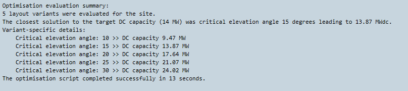
Several details about the optimisation process and the variants evaluated are displayed in the Scripting Results Log.
If the user decides to run the energy calculation as set by runEnergyCalculationForOptimizedLayout, the energy calculation run will then start, and the results will be saved in the defined directory assigned to parentResultsFolderPath.
// Print summary of optimization script
Toolbox.Log(""); Toolbox.Log("Optimisation evaluation summary:");
Toolbox.Log(string.Format("{0} layout variants were evaluated for the site.",
    DcPowerEstimatedCapacityPerLayout.Count()));
Toolbox.Log(string.Format("The closest solution to the target DC capacity ({0} MW) was critical elevation angle {1} degrees leading to {2} MWdc.",
    targetDcCapacity, closestLayout.Key, Math.Round(closestLayout.Value / 1000, 2)));
Toolbox.Log("Variant-specific details:");

foreach (var pair in DcPowerEstimatedCapacityPerLayout)
{
    Toolbox.Log(string.Format("\tCritical elevation angle: {0} >> DC capacity {1} MW",
        pair.Key, Math.Round(pair.Value / 1000, 2)));
}

if (runEnergyCalculationForOptimizedLayout)
{
    // Set the parent folder to store all the results and create it
    Directory.CreateDirectory(parentResultsFolderPath);

    Workbook.CalculationSettings.SaveResultFiles = true;
    Workbook.CalculationSettings.ResultFilesFolder = parentResultsFolderPath;

    // Run the energy calculation on this site layout.
    // This will use the current settings in the 'Setup yield calculation' task,
    // so make sure they are set as you wish (2D/3D, local/cloud).
    Toolbox.Log(string.Format("Running the energy calculation on site \"{0}\"",
        finalSiteLayout.Name));
    EnergyYieldCalculationScenario scenario = Toolbox.ExecuteEnergyCalculation(
        finalSiteLayout.Name,
        Workbook.CalculationSettings.SolarResource,
        Workbook.CalculationSettings.SiteLayout,
        Workbook.CalculationSettings.HorizonData);
}
An example of the optimisation process summary in the Scripting Results Log:
Results
Once you have run the script, a new parent folder should have been created containing a subfolder with the name "<workbookname> - <site layout name> (<current date and time>)", which includes the various result files that are saved out:
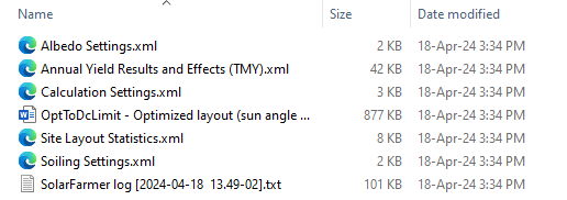
These include the calculation results and effects, along with various settings, statistics, a Word report and the latest SolarFarmer log file.
The SolarFarmer workbook will also contain the optimised site layout, with the results and effects diagram loaded (if the energy calculation was run). You may observe the several layouts, the optimal site layout and the several inverter DC/AC loading level within each layout region.
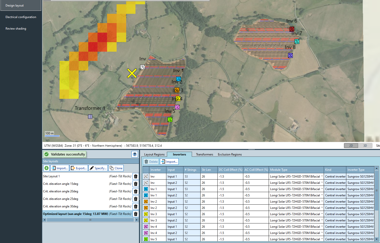 (click to enlarge)
Note
Get in touch (send an email to solarfarmer@dnv.com) if you need more assistance with this feature as it can be quite complex.