Shading Objects
SolarFarmer is built on a full 3D model and shading objects can be added to this model in addition to the terrain data. You can also define building regions to create buildings to place racks on and act as additional shading elements.
All these may cause shading effects on the PV modules.
- For 2D calculations the shading objects are ignored and not taken into account.
- For 3D calculations:
- For fixed-tilt rack sites the shading objects (and the terrain geometry itself) affect both beam and diffuse shading effects.
- For tracker sites the shading objects (and terrain) only affect the diffuse shading effects. They are not currently taken into account for the beam shading (only row-to-row shading is used for beam shading for trackers). This may change in future.
There are three ways to add shading objects in SolarFarmer: (1) using pre-defined 3D objects; (2) creating 3D objects; or (3) defining simple boundary-based shading objects. Details for each type are provided below.
Add Pre-defined 3D Objects
3D objects prepared in other software packages (such as Sketchup) that
have been saved in COLLADA (Collaborative Design Activity) *.dae format
can be imported into the SolarFarmer workbook and positioned in the
site. This is particularly suited to complex objects or objects that you
want repeated across the site area.
Go to the '3D Models' tab in the bottom panel in the Shading objects task.
a. Click the 'Import' button and select the COLLADA file.
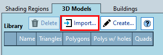
b. The object will be shown in the 3D Models Library in the bottom panel. Several properties will be shown.
c. You may add several objects to the library.
Select the object in the library that you wish to add an instance of to the map.
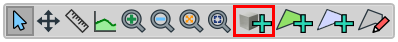
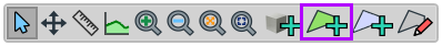
Select the 'Add 3D Shading Object' tool in the map's toolbar (grey cube with green '+' symbol highlighted in red below)
Click on the map to add an instance of that 3D object at the location you click
a. The map tool reverts to the 'Select' tool \(-\) click and drag the object to exactly where you want it.
Switch the map to 3D mode (the '3D button in the top-middle of the map) to view the objects in 3D.
Tip
Hold down the CTRL keyboard key whilst adding 3D objects to maintain the adding object functionality so you can quickly add multiple objects.
Create 3D Objects using Basic Geometries
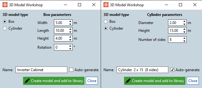
SolarFarmer allows you to create 3D objects based on basic cube and regular polygon geometries. These could be used in the shading scene to represent the shading effects from electrical cabinets (using the 'Box' 3D model type) or poles (using the 'Cylinder' 3D model type). To create a 3D object:
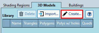
Click the 'Create' button in the '3D Models' tab in the bottom panel in the Shading objects task.
Set the type (box or cylinder) and the specific parameters for the 3D model type. Note that the name of the 3D object is autogenerated, but can be overwritten. Click 'Create model and add to library' and the model will be added to the Library section of the '3D Models' tab.
Similarly to the pre-defined 3D objects, add the created 3D objects using the 'Add 3D Shading Object' tool in the map's toolbar (grey cube with green '+' symbol, see above the toolbar screenshot in step 3 of 'Add Pre-defined 3D Objects').
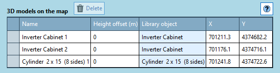
Any 3D objects on the map will be listed on the '3D models on the map' section of the '3D Models' tab with its name, location and reference library object.
Define Simple Boundary-Based Shading Objects
If you don't have access to a 3D modelling package, or you just want to create a quick 3D volume to approximate a forest, hedge or building, you can add a shading region.
Click on the 'Shading region' button in the map toolbar (green polygon with '+' symbol highlighted in purple below).
Click on the map to add points to form a polygon. Finish the polygon by clicking on the first point you clicked.
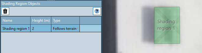
A new shading region object is added to the map and also to the table in the 'Shading Region Objects' table in the bottom panel.
Set the height of the shading region (height above the terrain) and the type:
a. 'Follows terrain' means that the height of the volume will be the same above each point. Useful for forests or hedges whose height you want to follow the terrain.
b. 'Flat top' means that the 3D volume will have a horizontal top face. Useful for modelling simple flat-topped buildings.
Again, switch the map to 3D mode to see the 3D volume.
Tip
You can also double-click on the last point to quickly finish a polygon.
Tip
You can adjust the height of the shading regions whilst in 3D mode to fine-tune the height of the shading regions.
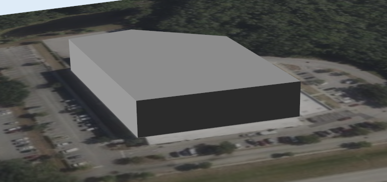
Building regions
Building regions are a way to add flat-topped buildings to your site.
Define a boundary representing the building, give it a height, and it will be treated as terrain.
You can then add one or more layout regions on top and any racks added will be placed on the building.
Any shading objects added within the bounds of the building region will also be placed on the building,
allowing you to add shading objects to represent air-conditioning units, chimneys and other features.
Add a new building region
Go to the 'Shading Objects > Shading objects' task.
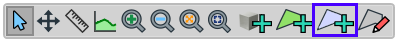
Click on the 'Building region' button in the map toolbar (light grey polygon with '+' symbol highlighted in blue below.
Click on the map to add points to form a polygon representing the building.
Finish the polygon by clicking on the first point you clicked, or double-click on the last point.
A new building region object is added to the map, and also to the table in the 'Buildings' table in the bottom panel:
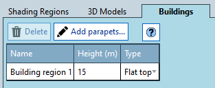
Set the height of the build region (height in metres above the terrain).
Leave the type as 'Flat top' - which means that the 3D volume will have a horizontal top face.
Pitched roof buildings are coming in a future release.Switch the map to 3D mode to see the 3D building volume.
Adding parapets to a building
Any building can have parapets (low walls around the edge of a building roof) with equal or different dimensions in each side wall. Any shading effects of the parapets will be considered when running the 3D calculation. The parapets can be added after the building is created.
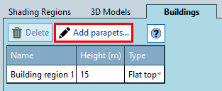
Go to the 'Buildings' tab in the bottom panel in the Shading objects task.
Click on the 'Add parapets...' button.
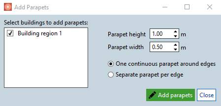
Define the properties of the parapets in the dialog.
- Select the specific buildings to add parapets on.
- Choose the dimensions (height and width) of the parapet.
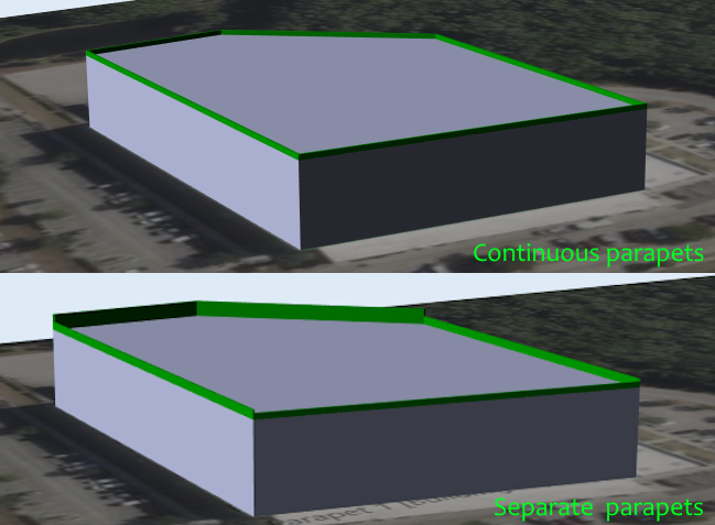
- Choose whether to add those a continuous shading object ('One continuous parapet around edges') or separate shading objects for each edge of the building roof ('Separate parapet per edge'). The latter will allow you to have different parapet heights in the roof top.
- Click on 'Add parapets' to add them to the map and as shading objects.
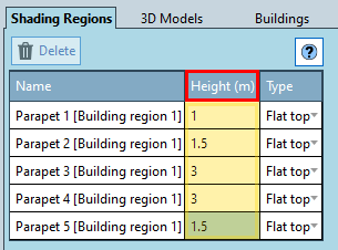
Review the parapets properties (height in metres above the building).
The parapets will appear as shading objects in the 'Shading Regions' tab, where you can edit the name, height and type of the parapets.
Leave the type as 'Flat top' - which means that the 3D volume will have a horizontal top face. When using a separate parapet for each edge, you can type the individual heights in the Height (m) column.
Switch the map to 3D mode to see the 3D building volume.
Two examples are shown below for parapets with equal (one continuous parapet option) or different heights (separate parapets per edge option with edited heights).
Add a layout region on the building
Now you have a building you can add a layout region on top of it, in which to place racks.
Go to the 'Layout > Design layout' task.
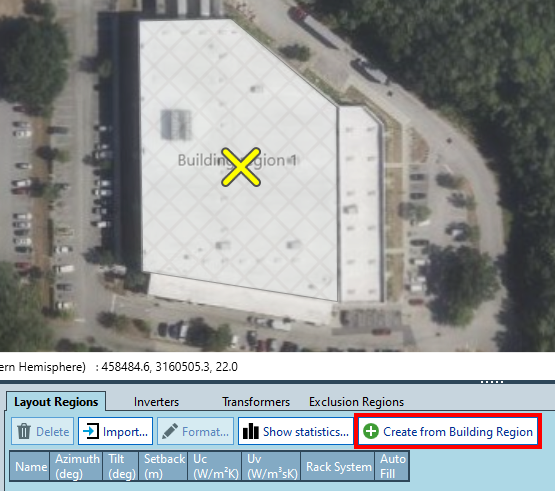
You can either add a polygonal layout region on top of the building as you would normally, or select the building region on the map, a 'Create from Building Region' button appears in the 'Layout Regions' tab in the bottom panel:
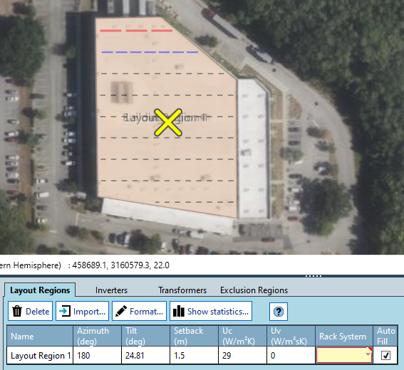
Clicking the 'Create from Building Region' button creates a layout region that fits exactly on top of the building (saving you some fiddly clicking!). It has an automatic setback of 1.5m (which you can change).
Choose a Rack System to add racks.
Make sure to update the 'Height of lowest edge from ground' property of your rack system. It defaults to 1m, which may be too high for racks placed on top of buildings.
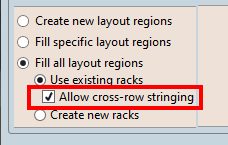
When adding inverters and strings, choosing the 'Allow cross-row stringing' option may help fill all the racks with strings.
Choosing this option does mean you will need to run the 3D calculation (cross-row stringing is not supported in the 2D calculation).
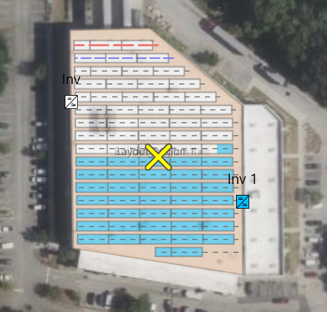
Viewing the map in 3D mode shows the racks placed on top of the building:
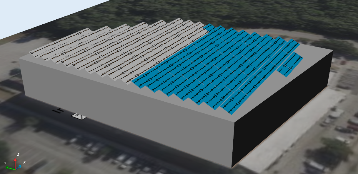 (BuildingRegions/RacksAdded_3D.png)
(click to enlarge)
(BuildingRegions/RacksAdded_3D.png)
(click to enlarge)
Adding shading objects to a building
Any shading objects (3D models or shading regions) that are added within the bounds of a building region will automatically get placed on the building's roof. You don't need to add additional heights or offsets.
Go to the 'Shading Objects > Shading objects' task.
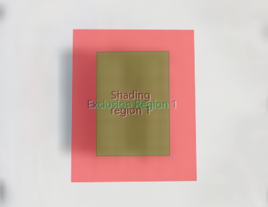
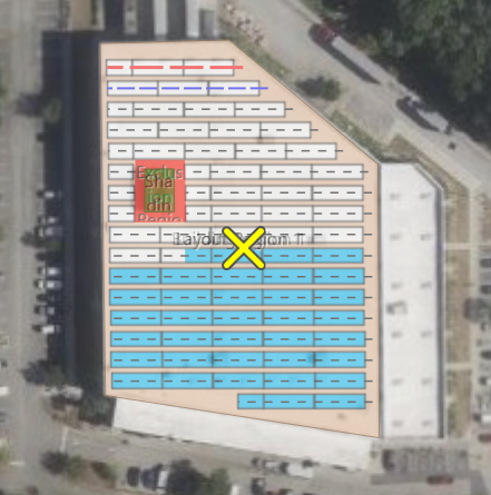
Add a shading region (or shading 3D model) on top of the building:
In this example, the height of 2m means that it will be extruded to a height of 2m above the building's roof.
Add additional exclusion regions around the shading objects if you want the shading objects to prevent the placement of racks (with auto-fill):
You may have to modify the locations of the racks and re-assign inverters and strings with the updated arrangement.
Viewing in 3D you can see the shading object placed on the roof amongst the racks:
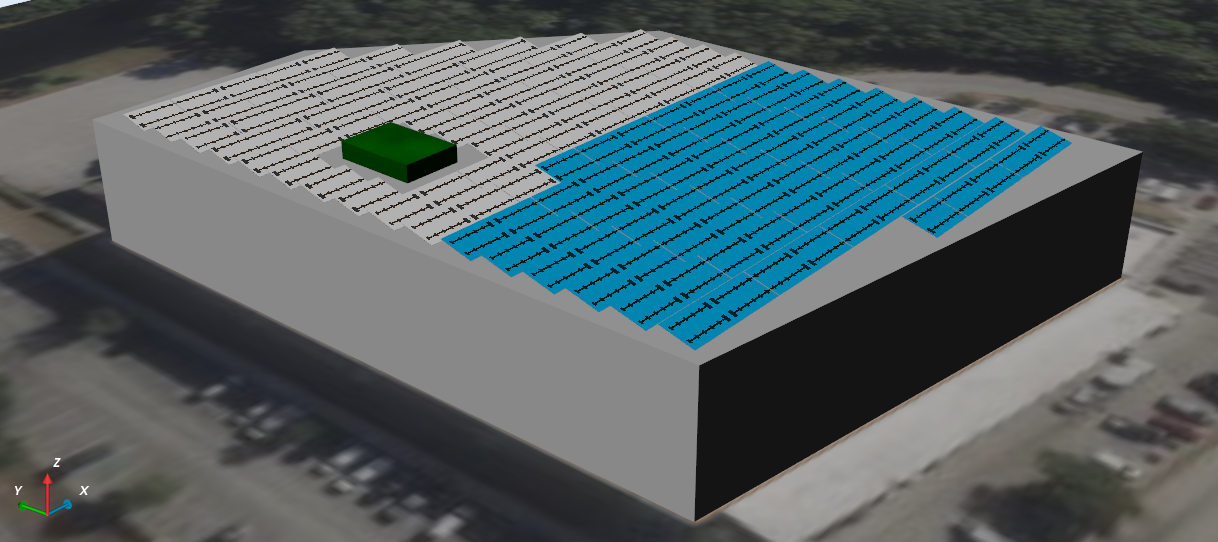 (click to enlarge)
Go to the 'Design layout > Review shading' task, run the shading calculation and view the map in 3D.
This allows to you view the shading effects on the modules from any shading objects and other buildings.
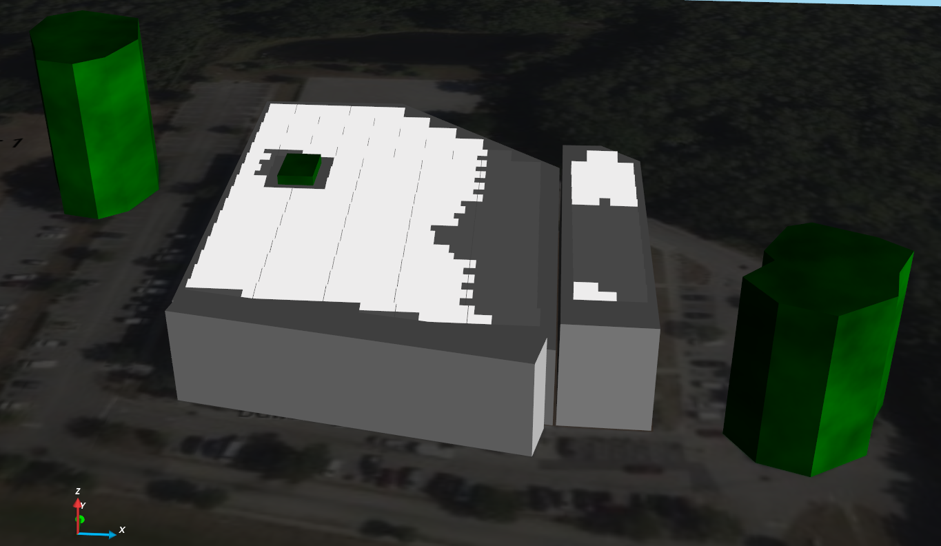 (click to enlarge)