Using Inverter Assignment Polygons
This functionality allows you to provide polygons (from a file) that are used to define areas to add an inverter (one per polygon). The racks/trackers within each polygon will be strung with strings for that inverter.
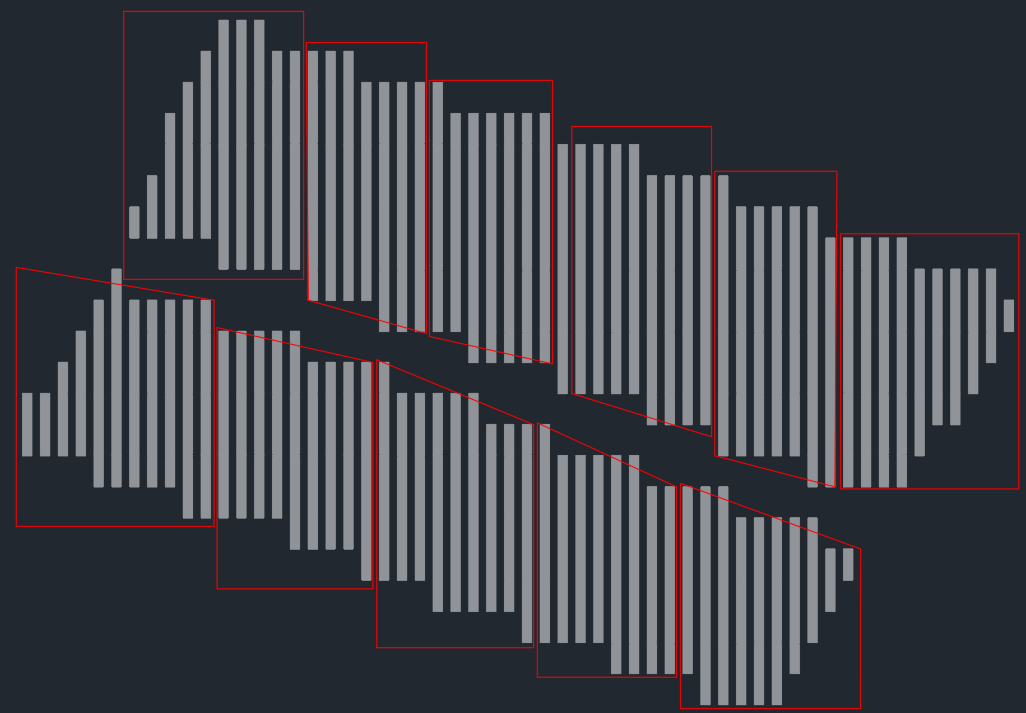
For example, with the following polygons (in red) defined in AutoCAD:
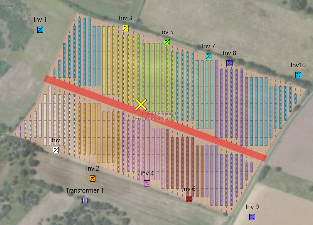
After exporting them to a shapefile, then using the 'Inverter Assignment Polygons' tool, the
resulting site layout looks like this:
In contrast, if you use the Specify Site Layout Tool to add and string inverters, SolarFarmer uses its own scheme for adding inverters and strings; generally starting from one end of the site and working its way across to the other. This can end up with a 'striped' effect, which doesn't always match what might happen in real sites.
This usually doesn't make much difference to the calculation results, especially with the 2D calculation, but sometimes you may wish to add inverters and strings in a way that more closely matches a real site.
The 'Inverter Assignment Polygons' tool can help you accomplish this.
Using the 'Inverter Assignment Polygons' tool
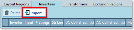
- Click on the 'Import...' button in the 'Inverters' tab of the 'Layout > Design layout' task screen
- The 'Import' dialog will appear, with the 'Inverter Assignment Polygons' tab selected:
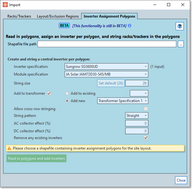
- Choose a shapefile that contains polygons representing assignment areas for inverters.
- The X and Y coordinates of the polygons should be in metres and in the same projection (e.g., UTM Zone 30) as the projection in your workbook.
- Any Z coordinates of the polygon points will be ignored.
- Choose an inverter and module specification.
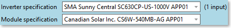
- These will be used during the assignment for the inverters, and the modules on the strings.
- These will be used during the assignment for the inverters, and the modules on the strings.
- Choose the string size.
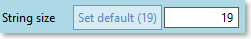
- It will set it to the default size for the current inverter and module specification combination.
- It will set it to the default size for the current inverter and module specification combination.
- Choose to add added inverters to a transformer.
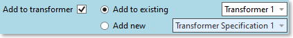
- You can add the inverters to an existing transformer instance (choose which one).
- You can choose to add a new transformer instance (choose the transformer specification).
It will then add a new transformer instance, and add the inverters to this new transformer instance.
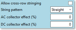
- Choose other options related to the stringing and new inverters.
- Finally, choose to remove existing inverters.

- If you already have inverters and strings in the site layout that you don't want to lose (and assuming that your polygons are for a different area of the site) uncheck this option.
- If checked, all existing inverter instances will be removed from the site layout before adding the new ones.
There is validation in the dialog to prevent you from making accidental mistakes. Once you're ready, press the 'Read in polygons and add inverters' button to start the process.
The process will then proceed (this can take a while if there are a lot of polygons and the site is large).
The output will be displayed in an output window in the dialog, giving a summary of what was done, and any errors
that may have occurred.
Close the dialog to view your site layout.
See The Occitaine Tutorial for an example step-by-step tutorial that includes a sample file for this functionality that you can try (specifically the Stringing of modules to inverters section).